
3D-Printed Assembly Jigs Save Time & Improve Quality
Building a prototype is hard. Producing multiples efficiently is harder. 3D print assembly jigs to make your medium-run assembly tasks easier and better

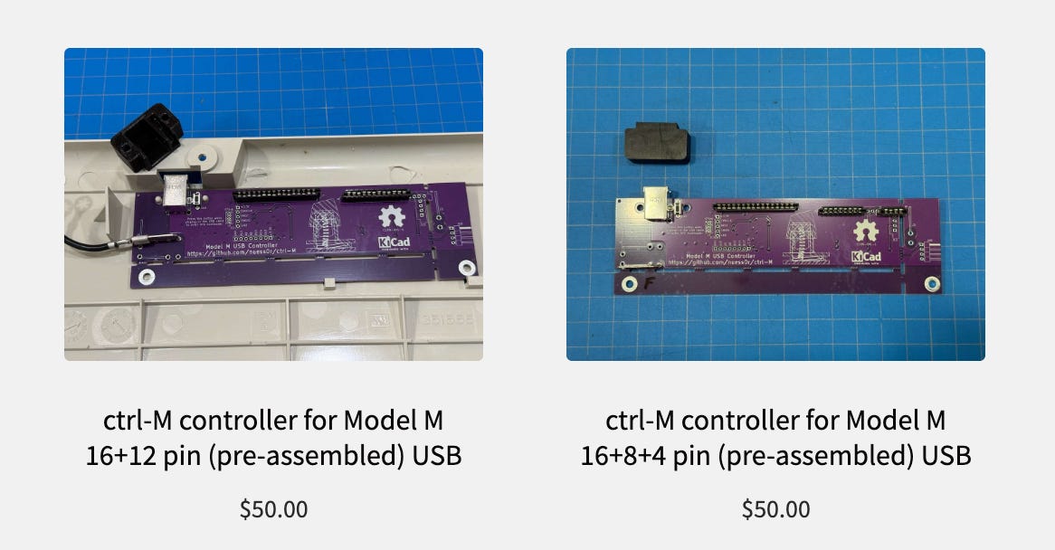
A few months ago, a man — a Swiss man named Christoph to be more specific — approached me with a project. He designed an open-source control board for the IBM Model M, but is no longer able to sell it to the US market due to recent changes in the international tariff situation.1 Per my experience with building a custom macropad, he thought I could potentially help him.
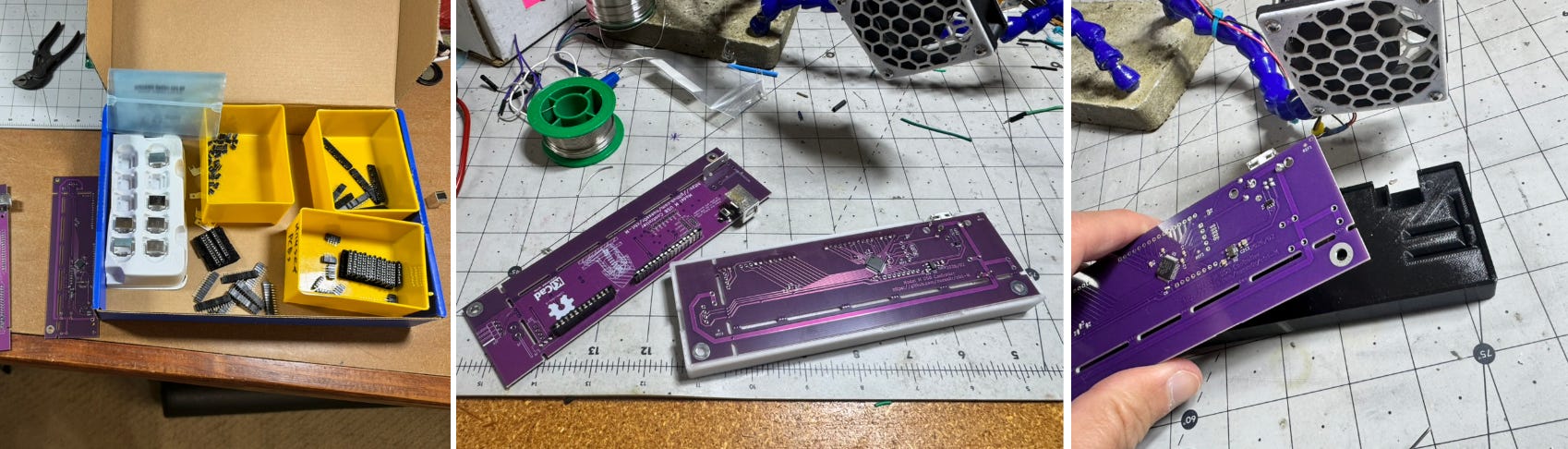
While apparently profitable, custom keyboard controllers are more of a hobby/interest for Christoph than how he makes his living, and he generously offered to help me get started final-assembling them here in the USA. I ordered the board from China to his specs, where they attach surface-mount components on one side.2

If you’re into offbeat engineering, real-world builds, and practical tech thinking, subscribe 👇
The other side’s thru-hole components, however, are more difficult to get China-assembled at relatively low volumes. Those bits are therefore soldered (literally) in-house, or in-garage to be specific. Assembling one or two of these devices with ad hoc holding setups (e.g. my solder squid) would be possible, but doing more requires a more efficient solution.
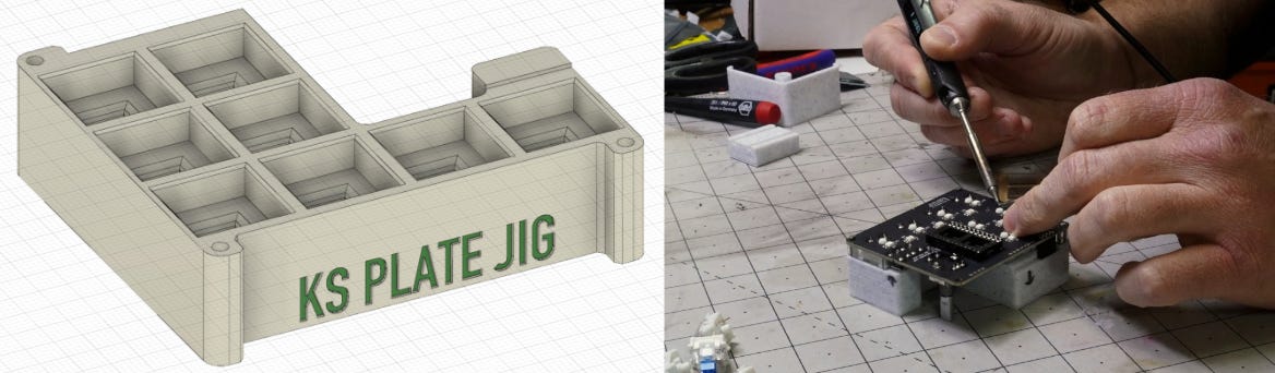
Besides preventing frustration, if I’m selling something, I want the assembly to be consistent. Randomly angled connectors is a literal and figurative bad look. So I did what I’ve been trained to do as a mechanical engineer and built a jig — i.e. a custom tool that helps with a specific job, or class of jobs, often holding something in place.
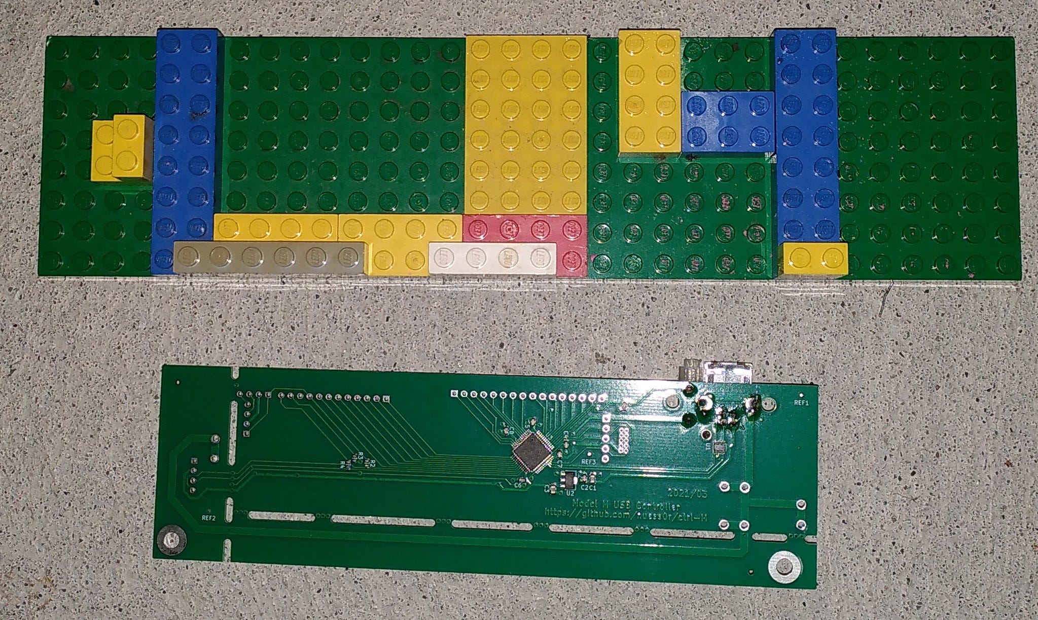
Notably, Christoph, the board’s originator, also made his own jig out of LEGO bricks. Apparently this worked well enough for him, though I believe he was attaching fewer components than I am.
Why 3D-printed jigs?
With all due respect to LEGO bricks, modern CAD tools + 3D-printing make building a customized assembly jig WAY easier than it was just a few years ago.
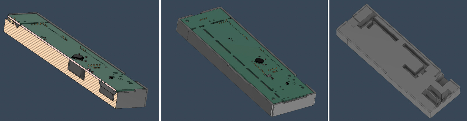
In this case, I exported the electrical board design as a STEP file (via KiCad), then imported it into Autodesk Fusion for the mechanical portion of the design.3 I then used the actual location of features on the 3D model to implement nooks and crannies on the jig where parts are held semi-securely while I solder them on.4
Less frustrating assembly, better results, what’s not to love? Well, there are a few caveats.
Tradeoffs for 3D-printed jigs
The position of jig cavities is dictated by the 3D model, and robotically produced by my 3D-printer, so placement will likely be correct (unless you make a careless error). Even so, there are some caveats to using 3D-printed jigs.
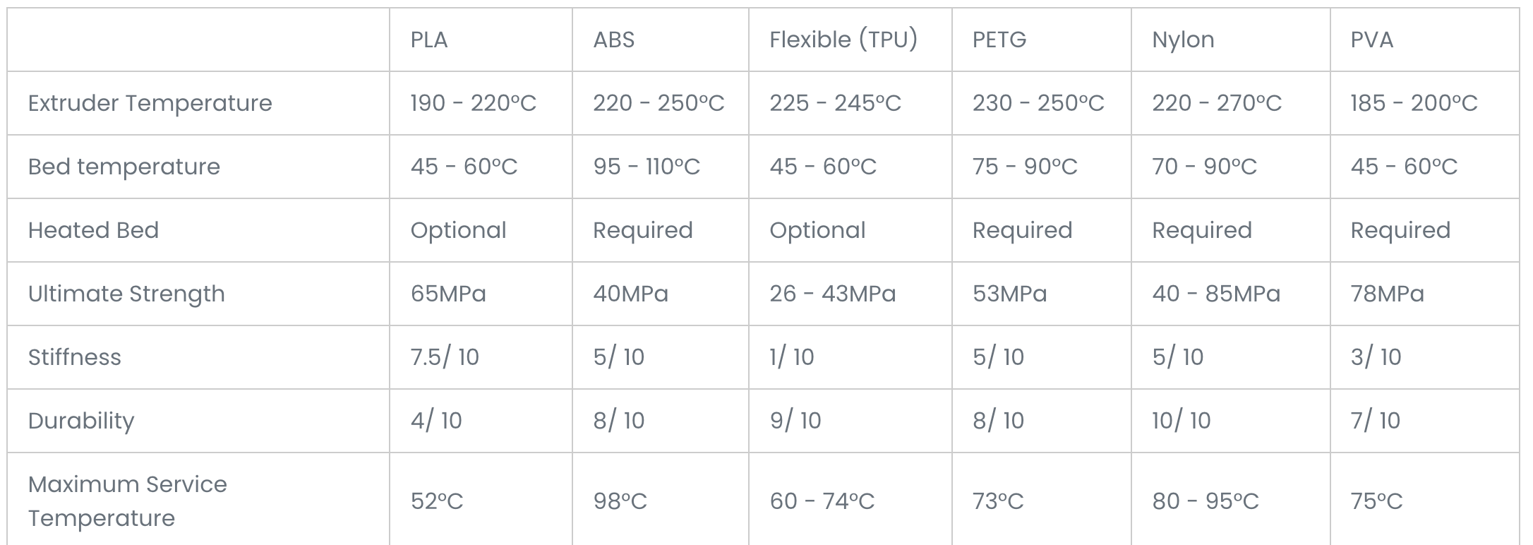
First, unless you’re using a rather exotic metal 3D printer, you’re limited to fairly soft, low-melting point materials. I’m using PETG, which withstands higher temperatures than standard PLA, but a soldering iron can still easily melt it. This was a problem with a metal blade component that sticks down and conducts a lot of heat during the soldering process. I had to leave more room here to avoid melting, and designed in surfaces that allow me to pry the board loose after processing.
Secondly, modification is more difficult. While taking off a bit of material in traditionally-machined metal jigs might mean throwing it on a milling machine or grinder, a plastic 3D-printed thing is more or less a what-you-see-is-what-you-get affair. If it’s not correct, toss it and reprint. Thus I’m on revision 55 of my jig, and each device was printed from scratch.
Finally, these jigs aren’t going to last forever. If you’re in a production environment where you’re going to make 100,000 of something, metal is probably the way to go. OTOH, with 3D-printing, a new one is just a matter of pressing a few buttons. You could rapid prototype a new jig idea via a 3D printer and then go with metal when you’re sure it’s correct, giving you the best of both worlds.
In this case, I’m not making 100,000 keyboard controllers. That’s a whole different game.
Another jig example
As originally outlined here, I made around 200 of my JC Pro Macro 2 devices to fulfill a Kickstarter campaign. I used the same sort of modeling techniques, and made several changes before settling on something that I thought was correct. I also used metal dowel pins on three corners to hold the board in place. It definitely made the assembly process much easier.
Of course, there’s some volume level where making a jig isn’t worth it. And if I just had to make one or two of either of these, manually fighting through might be the way to go. However, with the advent of 3D-printing and excellent design tools, the volume at which jigs make sense is much lower than it was just a few years ago.
A good project? A profitable project?
Considering expenses and startup costs, if I’ve make any money of this device, it hasn’t been much. However, it’s been a fun project, and as orders continue to ramp up, I hope this will become a steady, if moderate, source of income. You can buy them at ClickyKeyboards.com, which sells not just these controllers, but also the keyboards themselves and other accessories.
Besides a bit of techno-collaboration fun, it’s been a good learning experience. It’s also good material for Techadjacent.io! -JC
Techadjacent is where I share engineering ideas, builds, and practical tech analysis. Subscribe to get the next post in your inbox — published weekly👇
Thanks for reading! I hope you follow along on this Techadjacent journey. Fair warning: I can and do get a little off-topic in the footnotes.
Note: Some links may be affiliate
Addendum/Footnotes:
A few details on that paragraph:
Model M: i.e. those big, grey tank-like keyboards that have a generous numpad that you might have used years ago. While certainly a classic design, just thinking about using a non-ergonomic keyboard makes my wrists hurt.
He found me through indie electronics marketplace Tindie via my JC Pro Macro II macropad, which can run QMK firmware, the same thing that runs on his keyboard controller. You can find this and my other products on JC Devices. I wrote about Tindie here about a month ago, reporting on the fact that they’d been down for a while.
If you type all day, it’s worth investing some money and thought into your tools. That may mean an IBM Model M for you, for me it’s a split keyboard👇, custom macropad, and a Logitech trackball:
Boost Your Productivity and Comfort with These 3 Game-Changing Input Devices

The keyboard/mouse combo works well enough. If you occasionally type up emails, browse the web, play slither.io, and do other casual tasks on your computer, then average is most likely good enough.
Surface-mount components (AKA SMDs, surface-mount devices), don’t have any wires dangling off of them, and are (relatively) easy for a machine to assemble. The boards get selectively coated with solder paste, the components are placed… in place, and the whole board gets heated up for solder attachment.
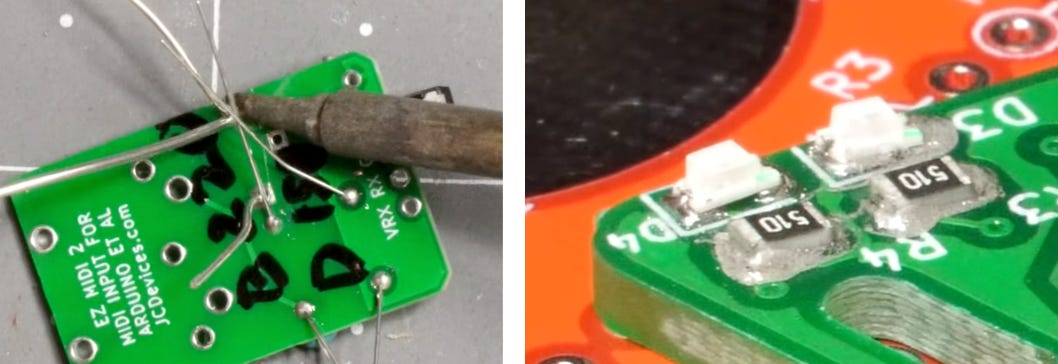
Thru-hole devices (THD) have wires that have to be stuck through holes on circuit boards. THD leads shown below on the left, SMD on the right. Imagine how much harder THD would be for a robot. AFAIK, this is generally done by hand.
Autodesk Fusion also has electrical CAD capabilities, which would theoretically allow the seamless integration of the electrical and mechanical parts of a design. This could certainly be beneficial, but I enjoy using KiCad. Also, KiCad is open-source and files are stored locally on your machine, both of which I like.
The actual keyboard controller jig is available here if you’d like to check it out. As is typical of jigs, it’s quite specific to one particular job, though perhaps it will still be instructive to someone reading.
Similar to how the nooks and crannies in a waffle hold butter and syrup, as opposed to pancakes where this tasty goodness just spills off the sides.
Starting with revision 0. So 6 tries at this. Because the first one hasn’t been revised at all. One could also say it’s version 6, but this nomenclature is generally how it works in the mechanical engineering world IME, so that’s what I stuck with.